
Welcome to Part 1 of an unknown length series on, as the title might have given away, reverse engineering the communications of a Texecom alarm system to it’s remote keypads (RKPs).
Motivation & Goals
I want to be able to set and unset the alarm system from anywhere in the house remotely and, since it’s a rental property, installing another rkp isn’t an option. I would like to be able to do this from my phone and, potentially, to integrate it with Home Assistant.
The imagined solution is something which emulates one of the 6 RKPs allowed as far as the Control Panel is concerned, participating in the RKP bus as if it were one and then offering differing levels of functionality by was of an esp8266 or esp32 programmed with ESPHome.
So, I need to set some goals for the project and to allow for implementations other than the imagined and I’ll set those by solution-less desired functions.
Step Goals
- Set and unset the alarm using a known user code
Stretch Goals
- Step Goals
- Read and report the current state of the alarm system
- Trigger the keypad panic alarm state
Leap Goals
- Step and stretch goals
- Fully emulate anything an RKP can do
Starting Point
I don’t know if this is possible and after a couple of evenings searching I haven’t found anything to suggest anyone has been down this road before. The closest example i’ve found is someone emulating keypresses on a Control Panels keypad using mechanical relays (https://community.home-assistant.io/t/make-the-texecom-veritas-8-smart-ish/236702).
Considering the cost point the systems are sold at this should be relatively simple once we can interface with the bus.
There is a backup plan; as mentioned before a previous project has emulated keypresses to be able to art some smarts to a very similar alarm system. I can do this in a more elegant way as it’s a simple scanned keypad; It not square but the premise still applies.
A pair of 8-to-1 analog mux/demux will do the trick with their common ports connected and their data lines connected to the row and column lines of the keypad. The address of one mux selects a row and the address of the other mux selects a column. If I maintain this at least the scan period of the RKP it will register a keypress as if one had been and hopefully wait for it to be released before accepting the input again.
Assumptions
Let’s kick things off with my assumptions going in and my justification for them.
RKP Bus Physical & Link Layer
What’s happening on the wire is electrically compatible with either RS-422 or RS-485. The instruction manual description of how RKPs can be wired implies a multi-point bus in star or daisy chain configuration and a cost optimised product like a basic alarm isn’t going to invent something new for the physical layer. This can’t be a UART like bus as they expect to be point-to-point. You’d have to add bus arbitration and a high-Z bus state for it to be possible. The bus needs to be multi-leader capable since either side (Control Panel or RKP) could initiate a bus transaction. This eliminates I2C like buses which sources online note other alarm systems use.
RKP Bus Transport Layer
Communications on the wire occur in the clear where there is no encryption or rolling code is in use. The product is cost obviously cost optimised and encryption would dictate more powerful MCUs. A rolling code would need a synchronisation mechanism to get all RKPs in sync when a new one joins the bus which can happen at any time. This isn’t impossible but when all bus items have physical tamper protection which protects bus connections and new bus stations have to go through a passcode protected joining process.
Every key press on an RKP produces the same output to the Control Panel. There may be a CRC sent to the Control Panel with a key press but we could map the value for every key press as it’ll be the same every time.
RKP General Operation
The Control Panel may produce a heartbeat on the RKP bus initiated by Control Panel to check RKP status in a response. It could also be initiated by the RKP’s periodically to communicate tamper status due to no dedicated tamper contacts.
Approach
The first step is to buy an RKP as they’re only £40 brand new and it lets me poke about without risking an alarm system which needs to remain functional. The main thing I want to understand right now is the electrical spec of the comms bus and what I need to do to RX from it.
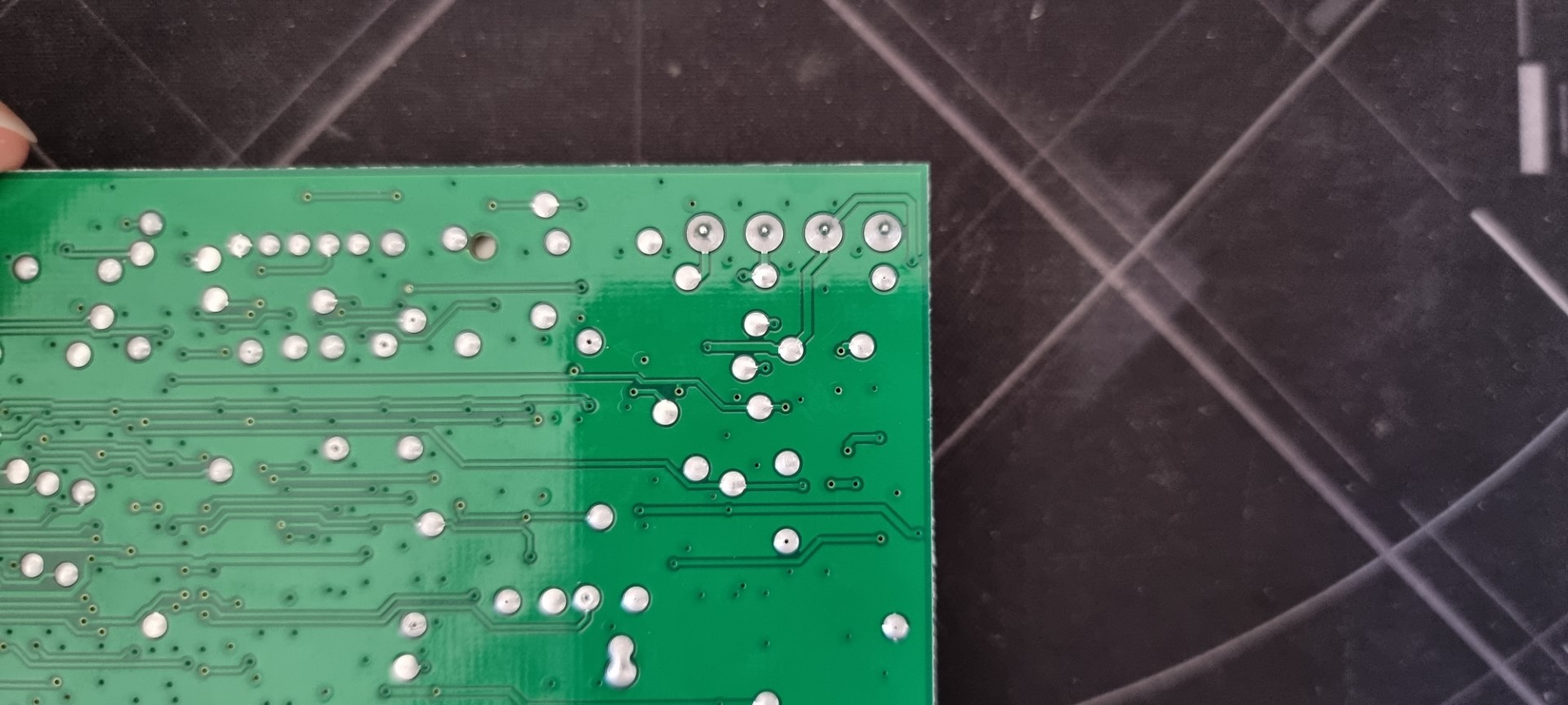
Once I’ve got one then I can examine PCB for any clues which could help me down the line. Hopefully it’s only a 2 layer board since there doesn’t seem to be a lot on it from pictures i’ve seen. It also appears to have been designed in a slightly old school, “one layer for horizontal traces and one for vertical traces” way.
Hopefully it can tell me how the bus transceivers built. If they aren’t using an off-the-shelf (OTS) bus transceiver IC then I could use it as a reference for building my own.
If the firmware stored in an EEPROM on the PCB I can dump it and go looking for the portions of software to do with communications and what the internal comms logic is like. Alternatively, If there isn’t an EEPROM, the MCU is known and able to have it’s firmware read out then i can do the same sort of thing.
Finally, applying power to examine signals at it’s bus connections is worth doing. Ideally it’ll just spit out things it hopes are going to arrive at the Control Panel out and give me lots of yummy insight… ideally.
Results
PCB


I believe it’s only a 2-layer board. It doesn’t look complex enough to warrant the extra cost associated with a 4-layer design and i can’t see and layer markings which suggest otherwise. I could try a bright light source and see if and internal structure is present despite the zone pours top and bottom.
Microcontroller
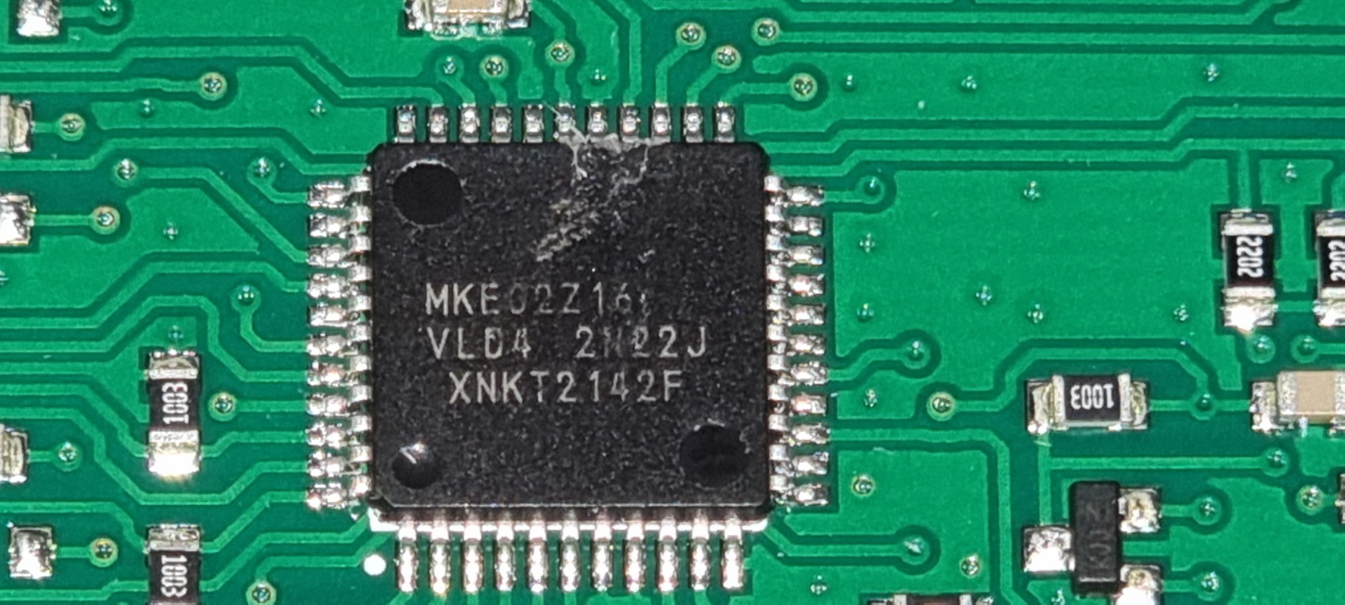
The MCU present appears to be an NXP Kinetis E series and I’ve found 5 pins which look like a programming interface. There’s +5v and Ground and then 3 pins which go to the MCU. The MCU markings are as follows, “MKE(G/0)2Z16 VL04 2N22J XNKT2142F”. The “VL04 2N22J” part comes back with an interesting result on an errata sheet for that version of a Kinetis E part which suggests the part number is in fact “MKE02Z16“. Which is a bargain basement 5 V, 40 MHz, Cortex-M0+ MCU with, “Home Security and Surveillance” as a suggested use case. Not many built in peripherals but the right amount of processing power for the job it’s doing. This could be a promising path to poking at it if the programming interface hasn’t been disabled.
RKP Bus Transciever
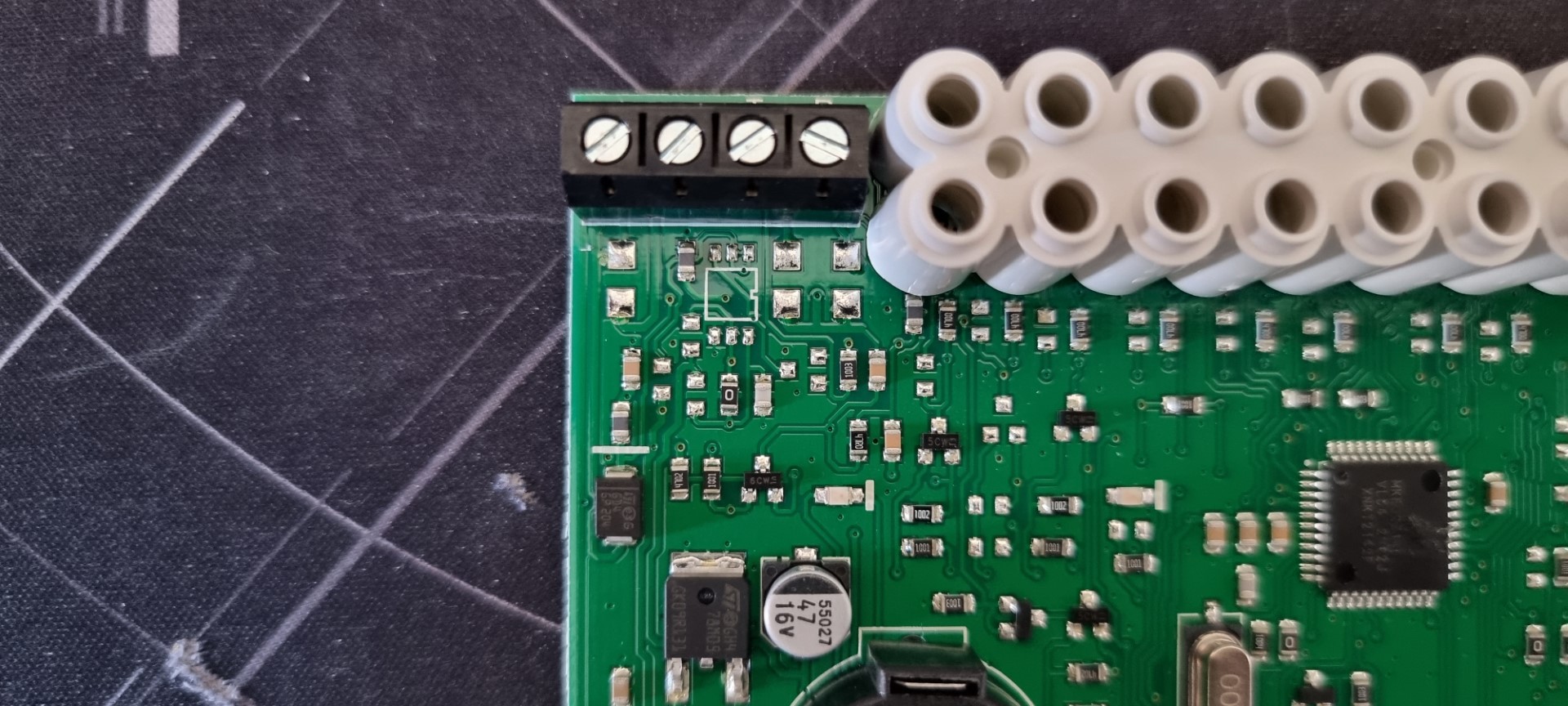
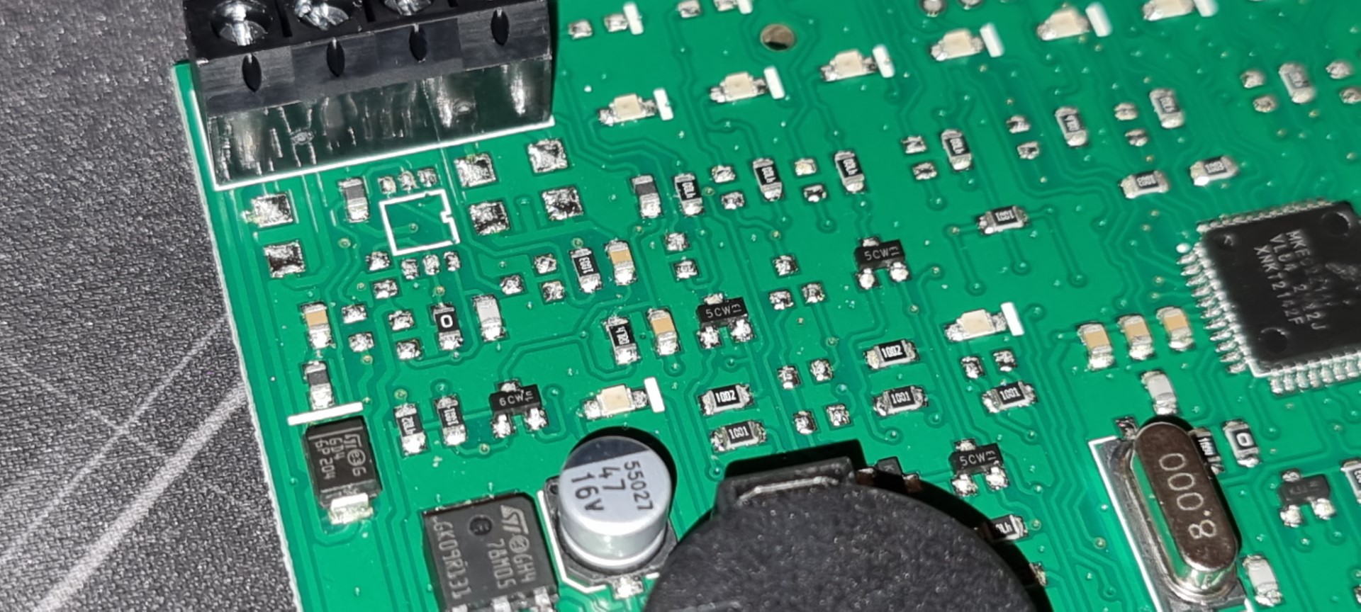
There’s no obvious line drive or but transceiver IC but looks like there may have been a footprint for one and the implementation which is there seems to be mixed in with the power regulation circuitry.
The device powers up normally according to what’s expected in the installation manual but locks up once a button is pressed with no activity on T or R lines. I’m not assuming the labels mean transmit and receive so I’m watching them both at the same time. It could be differential pair labelled to obfuscate it but it’s not behaving like one.
Powered up and resting the R line is pulled high to 12 V by what I’d guess is a few k-ohms as it can be pulled low by 600 R. The T line is low but very a weak pull-up (between two fingers on the same hand) can pull it up so it appears to be high impedance.

From the examination i’ve performed so far the PCBs implementation of line driving not obvious but my working theory is it’s a bi-directional MOSFET level shifter like that shown above.
Conclusions
- RKP key presses are confirmed with a response and without confirmation the RKPs state machine locks up waiting for a response from the Control Panel
- RKP may have to be initialised by an active Control Panel at least once to do anything
Further Work
- Try to power up whilst watching for comms activity with some pull on T and R lines.
- Monitor a functional RKP bus with an oscilloscope to try to understand the protocol and bus states.
- Interface with a functional RKP bus electrically using a level shifter to try and receive data from it.
- Initialise the new RKP and then remove from working system and see if it changes it’s bench behaviour.
Look out for Part 2!